




Leave feedback on the product


LXW5-11 limit switch

Shipping costs are not included in the price.
Shipping costs are not included in the price.
Product code: P-KRAN-0009
Share the product card


Ask about the product
The personal data controller is Graf-Art Sławomir Kulbida. We process it to respond to the inquiry. More information about the processing of personal data can be found in the privacy policy.

LXW5-11 limit switch
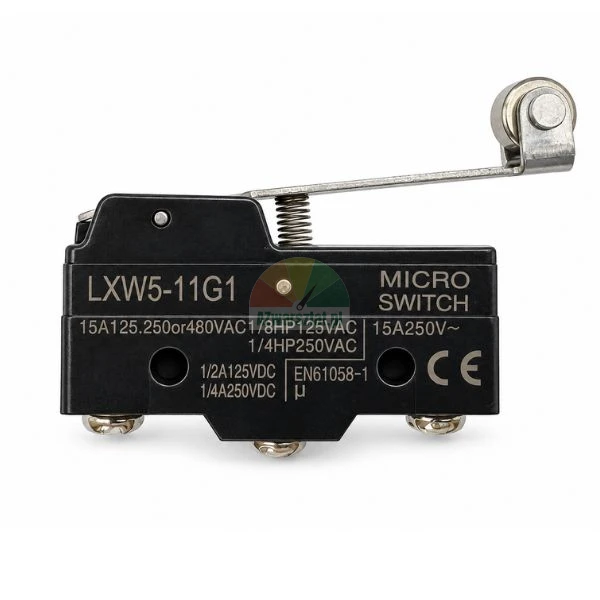
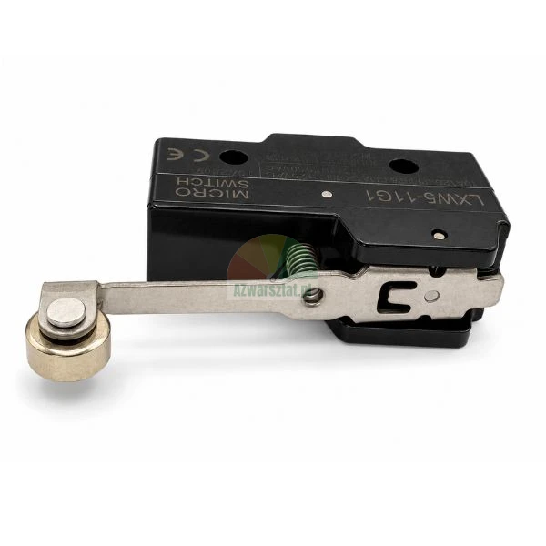
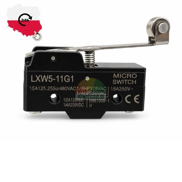
The LXW5-11 limit switch, as shown in the photographs and designated LXW5-11G1, is used to detect the position of a mechanical component and to disconnect or switch a control circuit. It functions as an end-position control, a movement lock or a mechanism to prevent further movement.
The G1 version has a long lever with a roller. The roller reduces friction when the control element comes into contact with it; therefore, the switch can be activated by a moving profile, cam, stop or machine component without the metal lever sliding across the surface.
Technical data
| Model | LXW5-11G1 / LXW5-11 |
| Actuation type | Long lever with roller |
| Contacts | 1NO + 1NC switching configuration, with common contact |
| Rated current as marked on the housing | 15 A at 125/250/380 V AC 1/8 HP at 125 V AC 1/4 HP at 250 V AC 1/2 A at 125 V DC 1/4 A at 250 V DC |
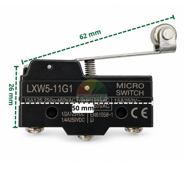
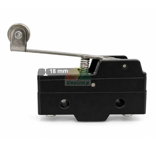
| Dimensions as shown in the photograph | Housing approx. 50 × 26 mm; length of lever with roller approx. 62 mm; height of lever section above housing approx. 18 mm |
| Markings on the housing | EN61058-1, CE |
Important when selecting: the symbol LXW5-11 does not specify the housing itself, but the entire product range. Before ordering, compare the lever position, arm length, roller diameter and direction of operation, and the mounting hole spacing with the switch fitted to the machine. The G1 variant has a long roller lever and is not a direct replacement for versions with a shorter lever, a pin or a panel roller.
Selection and installation in the mechanism
The contact element should press the roller in the direction of its rotation, rather than coming to rest on its edge. A high-friction side impact may bend the lever, knock the roller shaft out of position, or transmit forces to the housing that exceed those required to switch the contact.
The lever must not be used as a mechanical travel stop. The switch should receive a signal before reaching the end of its travel, whilst a separate stop should be used to bring the assembly to a proper halt. Pressing the lever against the housing during each cycle accelerates wear of the mechanism and may cause the switching point to shift.
According to the TENGEN LXW5 series catalogue, the LXW5-11G1 model has an actuation force of 0.35–0.85 N, whilst the return force is greater than 0.15 N. A low actuation force is advantageous for controlling lightweight components, but it also means that the lever should not be burdened by the weight of a cable, a guard or an accidentally positioned guide element.
Signs of wear and effects on the machine
- The machine stops at varying points despite the component being in a consistent position — this may be caused by wear on the roller shaft, a bent lever or an unstable contact switching point.
- The control system only responds when the lever is pressed firmly — this often indicates wear on the quick-switch mechanism or excessive friction on the roller.
- The motor, solenoid valve or contactor remains energised after the end of travel has been reached — the limit switch may fail to open the NC contact, or the wire at the terminal may have a loose connection.
- The roller rotates with resistance or stops as it approaches — in this case, the control element begins to scrape against the lever rather than rolling over it, which rapidly alters the geometry of the operating point.
- Intermittent faults that cannot be reproduced when the machine is at a standstill may be caused by vibrations and momentary loss of contact at worn contacts. In motion control applications, this symptom may cause jerking, a cycle restart or the machine to stop at a random position.
With inductive loads, such as the coils of contactors and solenoid valves, the actual load on the contacts may be greater than would be indicated by the rated current alone. If the circuit-breaker is operated directly in such a circuit, check the surge suppression method specified by the machine manufacturer and do not exceed the values stated on the housing.
Application
The switch may be used in mechanisms requiring position control, locking or an end-of-travel signal, provided that the mounting dimensions, roller position and electrical parameters are compatible with the specific machine. The product data does not include a list of compatible models of hoists, mounting machines or balancing machines; therefore, selection must be made on the basis of the installed switch and the control circuit diagram.
Opinions
If you've added a review and it doesn't appear on the list, it may be pending moderation.
Leave feedback on the product
Do you need help?

Go to the blog.
Talk to our customer service team.
Monday to Friday from 9:00 AM to 3:00 PM.
Frequently Asked Questions
What cables do I need for my two-post lift?
Check the rope termination. If there are any markings on it, the total rope length is very often indicated as well, e.g., L8920. This means the rope length is 8.92 m.
Additionally, to correctly select the rope, you need to provide the following technical parameters:
- Rope diameter – measured in the middle section (e.g., 8 mm, 9 mm or 10 mm)
- Thread – diameter (e.g., M16)
- Thread – length – length of the threaded section (e.g., 14 cm)
The drawing below shows the parameters that must be provided when ordering the rope:
What is my machine's model?
- Find the nameplate on the device – it usually contains key information, such as:
- Manufacturer
- Device model
- Year of manufacture
- Serial number
- If you cannot find the nameplate and do not have the technical documentation, selecting parts based on the model may be difficult. In this situation, we recommend searching for parts by category, photos, and dimensions, which often allows you to precisely match the correct component.
Can I return or exchange the part if it doesn't fit?
If the ordered part doesn’t fit, you can return or exchange it within 30 days of the purchase date.
For the return to be accepted, the part must:
- be unused and undamaged,
- show no signs of installation,
- be sent back in its original or appropriately secured packaging.
We care about your shopping experience, so the return process is quick and hassle-free. If you have any doubts, contact us – we’ll be happy to help you choose the right part or guide you through the return process.

